When assessing homes, I see too many residential HVAC systems installed badly. This article outlines my thoughts on how residential HVAC systems can be installed better.
by Richard Keech 2024-08-03
Outline
Motivation. In my experience, heating and cooling systems are very often installed in ways that greatly limit their efficiency and effectiveness. Most of the reasons are obvious when you see them, but some are more subtle. Some relate to ducted systems, others related to split systems.
In this article I’m going to limit discussion to:
- common ducted systems, and
- split systems.
Exclusions. I’ll discuss hydronic in a separate article. Portable systems are out of scope, as are wood-burning systems. I have already outlined why we shouldn’t be burning wood here. I’m not considering gas-fired heating at all.
Best-practice guide. I feel that the things I’m pointing out here should be in an industry best-practice guide. The closest thing I can find to an industry guideline on HVAC installation is the Airconditioning Residential Best Practice Guide by AIRAH, from 2003. However, this guide is old and almost exclusively focusses on practical assessment and mitigation of noise issues associated with HVAC systems. It doesn’t address the practical issues discussed here.
Goal. The goal of this article is to help consumers make better choices when purchasing heating and cooling, and to help them better understand the operation of their existing system and its relation to thermal comfort. In addition, I hope this will promote positive discussion about the need for an authoritative Australian best-practice guide for residential HVAC.
Ducted reverse-cycle
I’ve written separately here about why I think common ducted systems are a generally poor idea. However, where a ducted system is chosen, the system should be designed and configured to have:
- Sufficient thermal capacity, considering the premises and climate zone;
- Ample vertical separation between outlets and return.
- A return-air unit that, in addition to having good vertical separation, is:
- reasonably central;
- large enough for the size and number of outlets;
- includes a filter;
- has an air-tight fitting to the building structure;
- Provides a clear air pathway from every outlet back to the return point(s);
- Ducting with excellent insulation;
- Adequate clearance around the outside unit;
- Appropriate location of temperature sensor(s).
These seven points are addressed in turn below.
Thermal capacity
Sizing HVAC systems properly depends on many factors, and I’m not going to try to cover off this in any detail. If the system is undersized, then it will struggle to give you good thermal comfort (unless you zone or close off some areas) and will need to work very hard, possibly reducing its service life. Undersized systems can also be less efficient because heat pumps work most efficiently when there is sufficient heat-exchanger capacity relative to the load. Undersized means smaller heat exchanger relative to the load. If oversized, then the risk is that it is noisier and more expensive than need be. Oversized ‘inverter’ systems can also have difficulty regulating their operating range low enough, leading to the system shutting off and on, instead of smooth inverter operation.
System ratings. Heat-pump systems have a rated heating/cooling capacity, expressed in watts or kilowatts. This is not the electrical power, it is the thermal power. Usually the systems have separate heating and cooling thermal ratings, and the heating rating is usually a little higher than the cooling rating.
Rule of thumb. A commonly used rule of thumb for system sizing is to allow about 150W of thermal capacity per square meter of conditioned floor space. This is a very rough rule of thumb for premises that are not thermally improved. So high-performance home (i.e., high star rating) might need much less than 150W/m2. A home with tall ceilings may need more than 150W/m2. The origins of this rule of thumb aren’t clear, but its use can be seen here, here and here.
Fair air. One free online tool to estimate the required capacity is Fair Air. This is from AIRAH, which is the Australian peak professional body for refrigeration air conditioning and heating. Use Fair Air to calculate required capacity one room at a time.
Vertical separation
Mixing is necessary. For best results, there should be vertical separation between outlets and return. This is because it’s important that the conditioned air mixes well within the entire conditioned volume. Heated air introduced out of registers in the ceiling cannot easily mix to floor level unless cool air is drawn out near floor level. Likewise, cooled air from floor level outlets will pool unless hot air is drawn out at ceiling level.
High-school science tells us that hot air rises. So, having both outlets and return at ceiling level is fighting basic physics.
Stratification. A common artefact of poor air mixing is stratification – a situation where there is a distinct layer of heated air above a layer of cool air. The practical implications of this is poor thermal comfort (hot head, cold feet), and systems that have to work harder than they should.

Poor air mixing doesn’t always mean distinct layers like this. It might be a more gradual change in temperature from ceiling to floor.
Common problem. In contemporary HVAC installation, I commonly see systems with both outlets and return at ceiling level. This situation is worst where the:
- home is two-story,
- home has poor draught proofing,
- outlets are in ceilings,
- only return is in the upstairs ceiling,
- main living area is downstairs, and
- home is built on an uninsulated concrete slab, especially if no carpets or rugs.
In situations such as these, poor winter-time thermal comfort and high running costs can be expected because conditioned air doesn’t get to the occupants very well, and the cold slab cannot be warmed. This leads to occupants being coldest closest to the floor. I suspect that this situation describes a great number of volume-built new homes in Victoria, where I live, and possibly other places.
Solution. Assuming ceiling-level outlets, which is the most common situation, the solution is to ensure that the design of the home allows for the placement of a central return-air point as close to floor level as possible on the ground floor. It requires suitable planning in the design and construction so the layouts ensures there is a suitable vertical pathway (‘riser’) through which the duct can pass.
A good arrangement. The appropriate location for the return is usually wall-mounted, at floor level, in a central hallway.
Work around. If you find yourself with this situation, experiencing the effects of poor air mixing in winter, and you cannot fix it properly, then you’ll need to use a ceiling fan on low speed where possible to mix up the air so that the heat energy can get down to floor level.
Return air point
In = out. The arrangement of the return-air point, beyond giving good vertical separation, needs to be able to capture all the air coming out of all the outlets. It also serves as a point where air can be filtered. Since air volume out (of all the outlets) equals air volume in (to the return), then if the return-air point is not filtered, it follows logically that the area of the return inlet should correspond approximately to the size of all the outlets put together. If the return air point is much smaller than this, it will be a point of flow restriction, causing increased air noise and increasing required fan energy.
Filter impact. In a good system, the return air point will incorporate an air filter. The filter is a slight impediment to the easy flow of air. To offset the filter’s effect on flow, the area of the inlet should, ideally, be even larger than the sum of the area of all the outlets. The filter needs to be regularly cleaned.
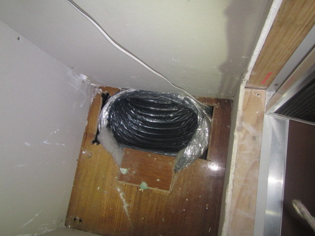
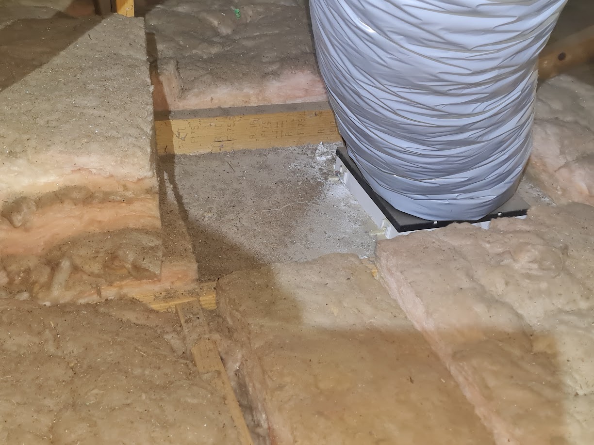
Air-tight. Behind the typical return-air grill is usually a box which interfaces to a duct. This box might typically be made within a plasterboard vertical void space which serves as a riser. It is common to see that this arrangement is not air-tight, and has substantial draught pathways into the same space that the ducts occupy, as in the photo at the start of this article. This shows the duct passing through a hole in the floor with large holes allowing draughts. Making this arrangement air-tight is critically important, to avoid draughts and ensure that all the air passes through the filter. See this excellent video from Efficiency Matrix for more about this. The return-air box should be insulated if it adjoins an unconditioned space.
An example of what not to do is to have the return point:
- at ceiling level,
- without a filter,
- that is too small, and
- is not air-tight.
Clear air pathway
Doors get in the way. Thought needs to be given in home design to how the air from every outlet is to make its way to the return point. This means that interior doors can get it the way. In my experience, this requirement for a clear air pathway is normally overlooked completely.
Induced return air. The fan will draw the most conveniently available air into the return air, instead of drawing air from distant heating outlets (especially if internal doors are closed), so it will ‘prefer’ air from gaps around external doors and windows, through vented laundries, bathrooms and toilets, and even ‘backwards’ through open exhaust fans. This outdoor air requires much more heating (or cooling) than recirculated air.
Undercutting. A common and simple way to do this would be to undercut any internal doors that stand in the air pathway between outlets and return. This most obviously applies to bedrooms. Undercutting the doors means to cut off enough of the lower section of the door to allow a gap big enough for the air to flow without significant restriction. The obvious problem with this is that it compromises acoustic privacy. As a rule of thumb, the area underneath the undercut door should be at least as large as the area of all the floor outlets behind that door, and ideally at least 1.5-2x the area to reduce air noise and pressure drop.
Another way to do this is to include some sort of pass-through vent or grill in the structure – possibly in the wall or door. An example would be this door-vent product.
The ideal way to achieve this clear air pathway is to have separate supply and return within each conditioned space. However, this is very rare, and usually considered to be impractical.
Insulation
Duct insulation
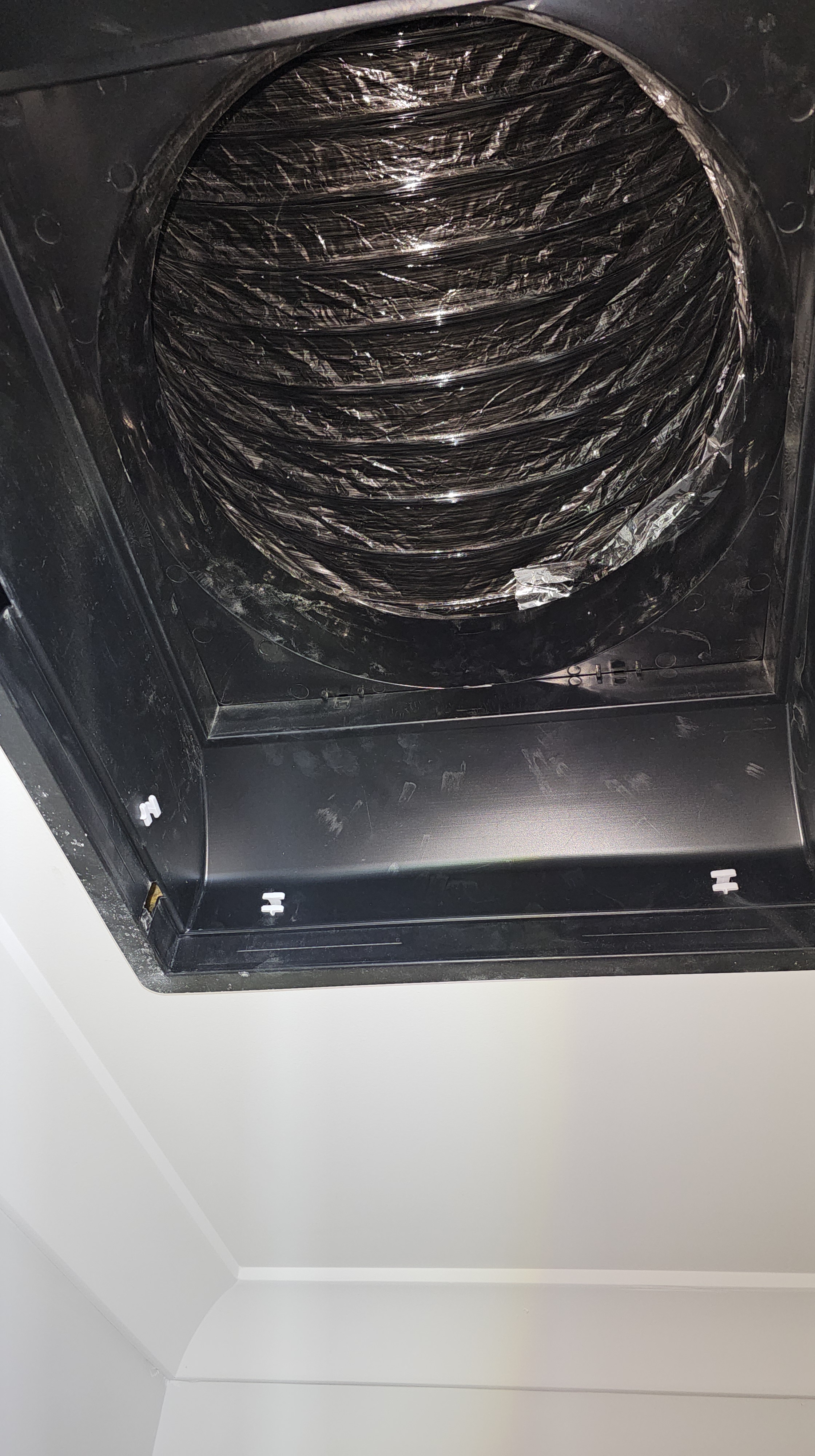
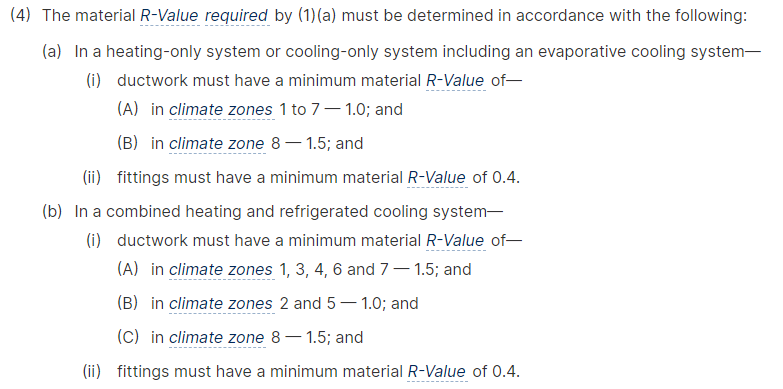
Normal practice in Australia is for ducting to be outside the thermal envelope. So, it is important to get ducts that have sufficient insulation. In the current version of the NCC (version 2022), the minimum requirement for insulation in ductwork for heating- or cooling-only systems is R1.0, except for Climate Zone 8 (i.e., alpine) where it is 1.5. For combined heating and cooling systems the minimum requirements is R1.0 in Zones 2 and 5, R1.5 in other zones. Refer here.
Note, for reference in applying these rules:
- Melbourne is Zone 6
- Sydney, Adelaide and Perth are Zone 5
- Hobart is Zone 7
- Brisbane is Zone 2
- Darwin is Zone 1.
Inside the envelope. For best results, in a new-build situation, consideration should be given to providing for some or all of the duct work to be within the thermal envelope. Any ducting that is within the thermal envelope would not normally need to be insulated.
Impact on other insulation
Ducts and vent registers need to be installed such that ceiling or floor insulation is not impacted.
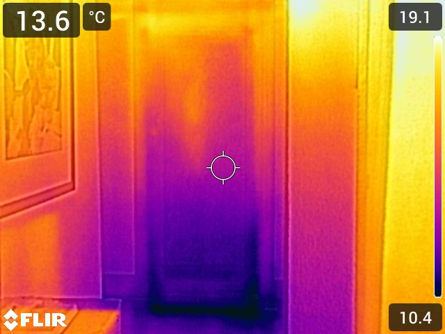
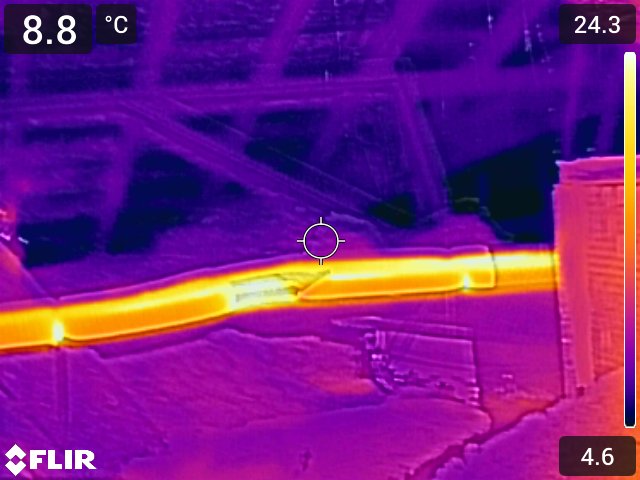
When specifying your ducted system, make clear the expectation that ceiling insulation around vent registers is to be made good, as per the ICANZ Insulation Handbook, Part 2. This will necessarily require cutting of the insulation so that it cleanly conforms to the outline of the vent register. I never see this in practice, but it is really important.
If you have a system installed, then check this, and make sure that the installer knows that you are going to check this and make them fix it if required. Checking using thermal imaging may be required.
Clearance
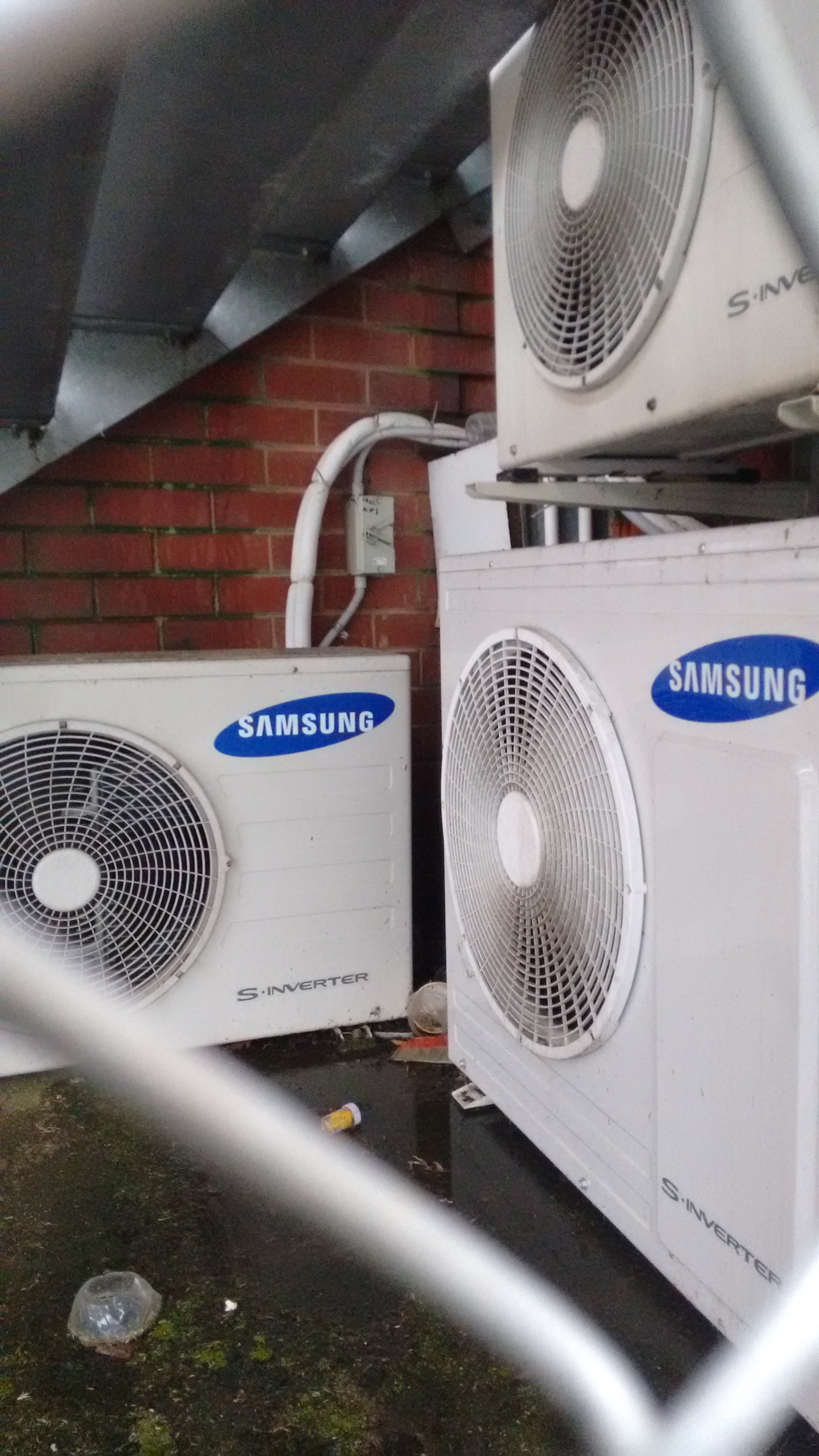
The air that is discharged from AC units needs to dissipate cleanly into the ambient environment. However, it is common to see outside aircon units will insufficient clearance from obstacles, especially fences. If discharged air cannot dissipate fully, then some will inevitably be drawn back into the unit. This reduces efficiency and effectiveness.
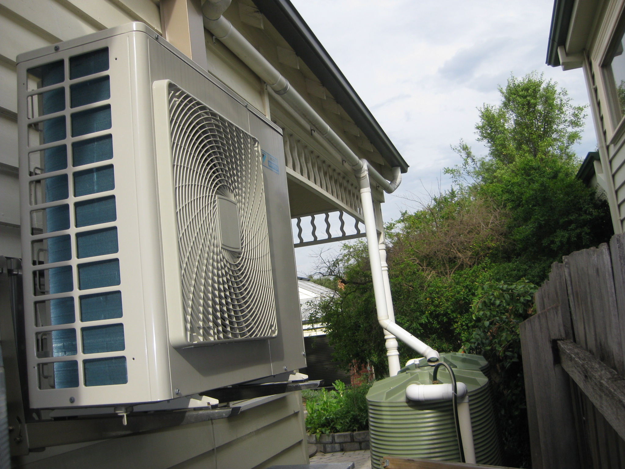
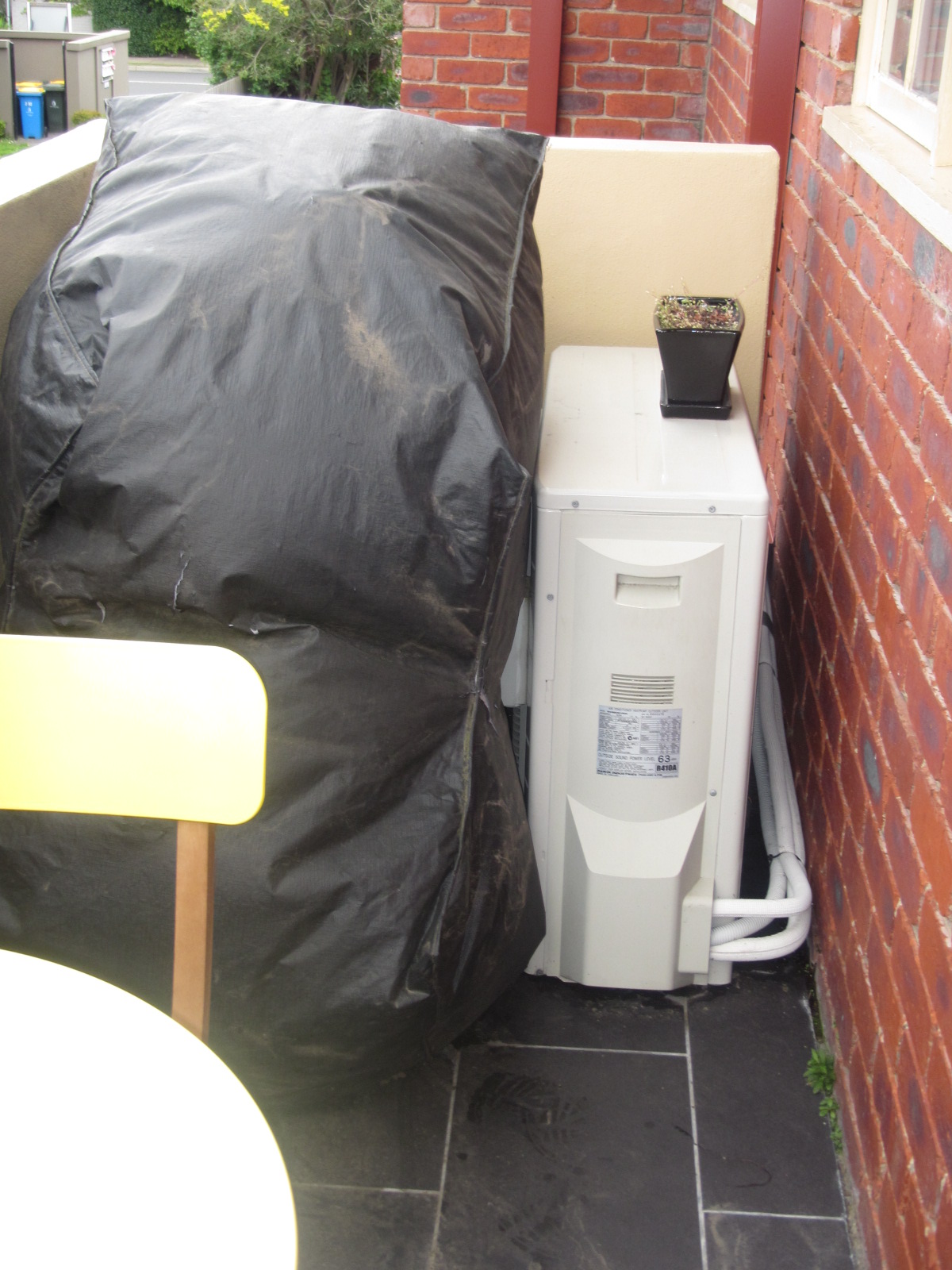
Even where the clearance meets the manufacturer’s minimum clearance requirements, it is probably still sub-optimal. The picture below shows a unit that probably meets manufacturer’s minimum clearance, but is, nonetheless problematic.
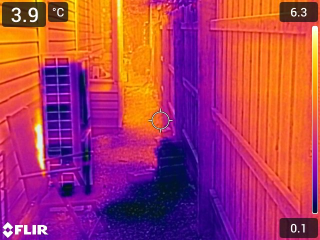
Mitigation. Where an AC unit discharges straight into a fence like this, one way to mitigate the impact is to fit the unit with a deflector so that more of the discharged air moves up and over the fence. Or, if possible, fence of the inlet from the discharged air. Or both.

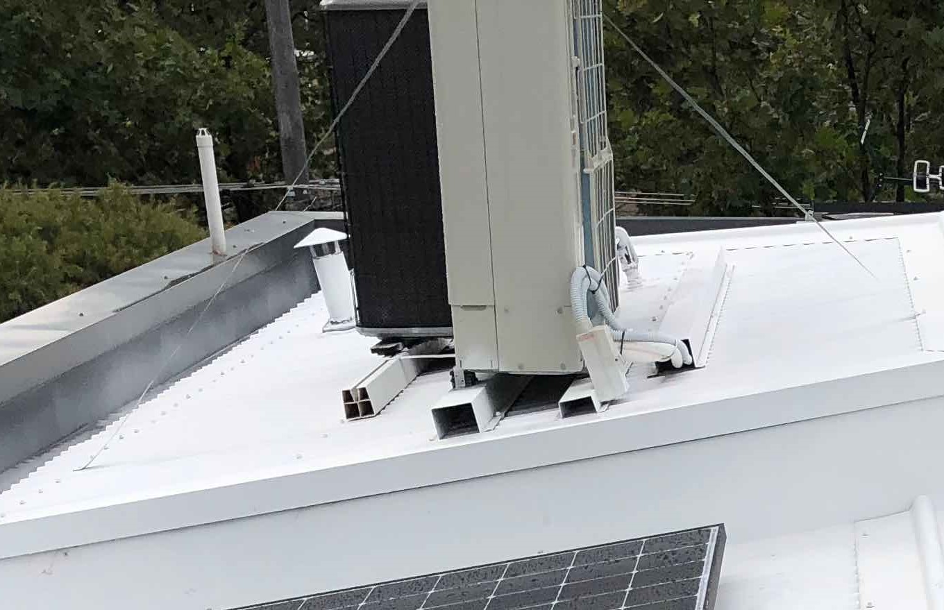
Another way to mitigate issues with clearance around AC units is to have them mounted on the roof, as shown below. If they are mounted on the roof and used for cooling, a light coloured area of roof around it can provide cooler air for the RCAC, improving summer performance.
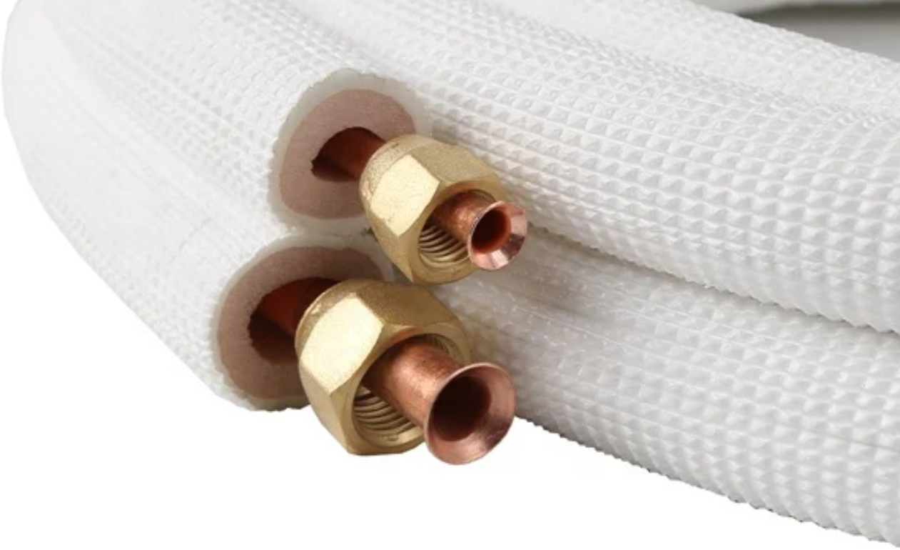
Pipe insulation
Running between the outside AC unit and the inside unit is a pair of insulated pipes. It’s important that the pipe insulation be:
- sufficiently insulating, and
- protected from UV degradation and physical damage.

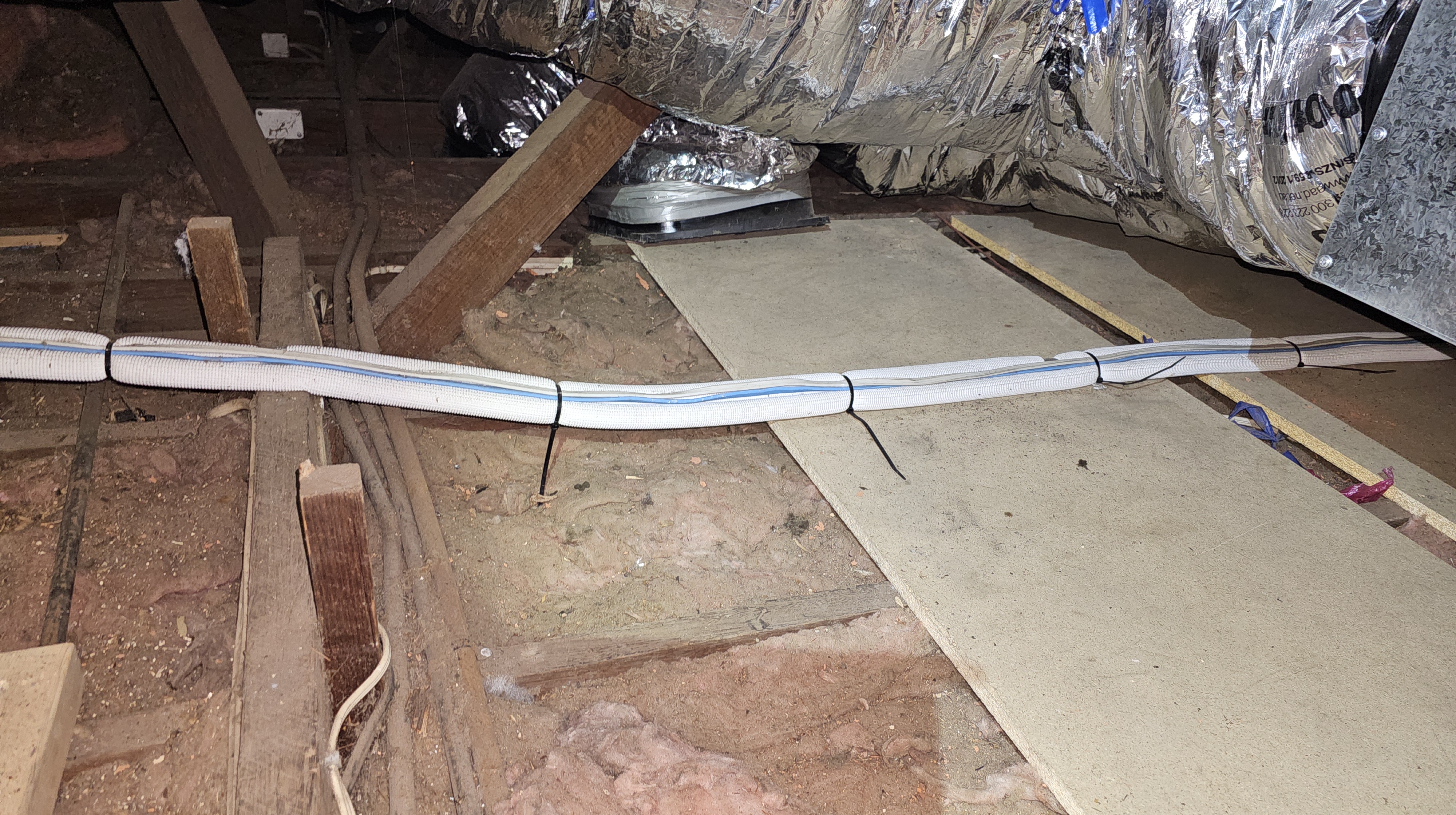
Better insulation. Sometimes there are long lengths of aircon pair-coil tubing passing through roof cavities and under-floor spaces. I suggest that adding extra insulation on this piping would be inexpensive and beneficial because the insulation normally found on these is only about 10mm-thick. The longer the pipe run, the more important it is to improve the insulation.
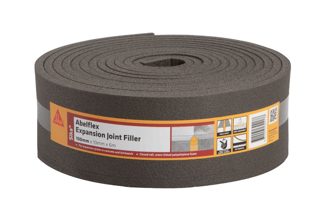
Where aircon pair-coil pipes are accessible, say in a roof void or sub-floor, then it might be possible to use expansion-joint filler foam (see below) to coil in a spiral around the existing pipe to increase the insulation of the pipe by about 2x.
Location of temperature sensors
Proper operation depends on the thermostat temperature sensor(s) being properly located within the home. The main things to check are that the sensor is not adversely affected by factors such as:
- direct sun
- nearby sources of heat like dishwashers or AV equipment
- thermal bridging, such as being on uninsulated walls.
Split Systems
Clearance
The same issues with clearance around the outside units apply equally to split systems as to ducted. However, with split systems the outside systems are typically more numerous and smaller. An option for improved clearance may be mounting the unit on an external wall to allow the discharged air to more easily dissipate. Wall mounting can also improve general utility by potentially giving useful space underneath the unit.
Sizing. Similarly, the same issues with system capacity apply with split systems. However, split systems are generally more efficient than central ducted systems, so slightly less system capacity is required, all other things being equal.
Other installation and design issues that apply to split systems:
- Building penetration,
- Pipe insulation,
- Choice of head units.
Type of ‘head’ units
The internal part of a split system (the ‘head’ unit) is most commonly mounted high on a wall. However, there are other types of head unit available from most vendors:
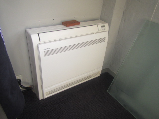
- Console. Head units at floor level (aka ‘console’ units) may be a better choice when the main use of the system is for heating, especially when the ceilings are tall. Delivery of heat from closer to the floor is often adventageous;
- Bulkhead. AC head units can be hidden away behind a discrete grill using a bulkhead unit. These units lack the air-control features of a normal head unit such as: vanes which can control the direction of the discharged air. They also may lack filters found normally on split systems;
- Cassette. AC head units can be recessed into a ceiling using a cassette unit. These systems are more often seen in commercial premises;
Building penetration
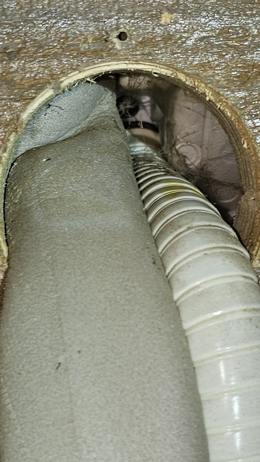
Fitting a split system to an inside wall requires penetrating the wall to allow pipes and cables through, to pass from inside back to the outside unit. Common poor practice involves a hole that is too large, and which is difficult to seal well.
These holes are typically hidden behind the aircon head units, and open up the wall cavity to draughts and vermin.
When making a hole in the wall, it would be a great help to:
- keep it no bigger than absolutely necessary;
- fit some sort of pass-through sleeve; and
- Use duct-seal putty as required.
Pass-through sleeve
A pass-through sleeve, fitted through the wall would prevent the interior void of the wall from being opened up. The idea is to allow the pipes to pass, joining inside to outside, without creating a pathway into the wall void.
A suitable product would be one of these available from Amazon for about $14. This has an inner diameter of 71mm, and requires a 75mm hole.
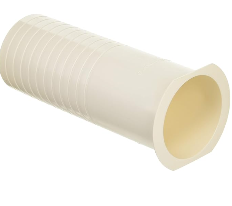
An improvised way to make one of these would be to use a section of PVC pipe with a flanged end. Perhaps use one of these 65mm PVC DWV floor flanges, with a short length of 65mm pipe. The idea would be that the flat flanged end would seal to the inside plaster wall. This represents under $10 of parts. The air-conditioner pair-coil pipes should then be able to be passed through the pipe.
With piping passing cleanly through the pipe, it should then be easy to pack out any gaps to prevent air or vermin passing through.
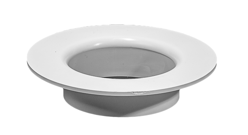
65mm PVC floor flange
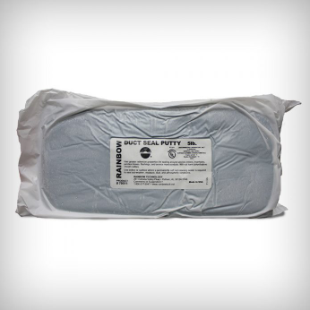
Duct-seal putty
Another product that can help make good the pipe penetration is duct-seal putty, for example from Rainbow Technology, available here or from Amazon here.
Mitsubishi Electric’s guide
Here’s a guide from Mitsubishi Electric on best practice for sealing pipe penetrations.